Oh hey, this is the Tylephone

The tylephone is a dope little synth I've been working on
oh man you're missing out on this pic

Guys, I'm happy to share that the Tylephone DIGITAL is live

Go ahead and give it a little play!

Want to make your own Tylephone?

Here is everything you need, including files, materials needed, and a quick build guide.

This is all available for FREE so if you want to support me, please subscribe to my channel
You could also buy me a coffee here

Submit a Question HERE and Check Below for Updates!


View Q&A


FIRST all of the necessary files are at my GitHub
However, if you want to modify the 3D .stl files, here are the Onshape project files!
(I definitely didn't optimize for printability. Feel free to make better ones!!)

Also, I've also put the 3D .stls on my Thangs store just in case you wanna check them out

Next, all the necessary supplies

Below are all the Amazon links you need.
FAIR DISCLAIMER I have not personally bought everything on this list because I had a lot of it lying around. Any thing that is "Tyler certified" has specifically been bought for this project and verified to work with it. Anything else has an explanation box. I have also included a list of possible options for tools, but the only really necessary tool for this project is a soldering iron. You can send the .stl files out to be printed by a service if you don't have a printer. The printer I recommended is just what I have, and not at all a full endorsement. You can probably find better for cheaper. Check out bambu lab
Stuff
Description Link Qty Cost Qty needed Cost needed Is it Tyler certified?
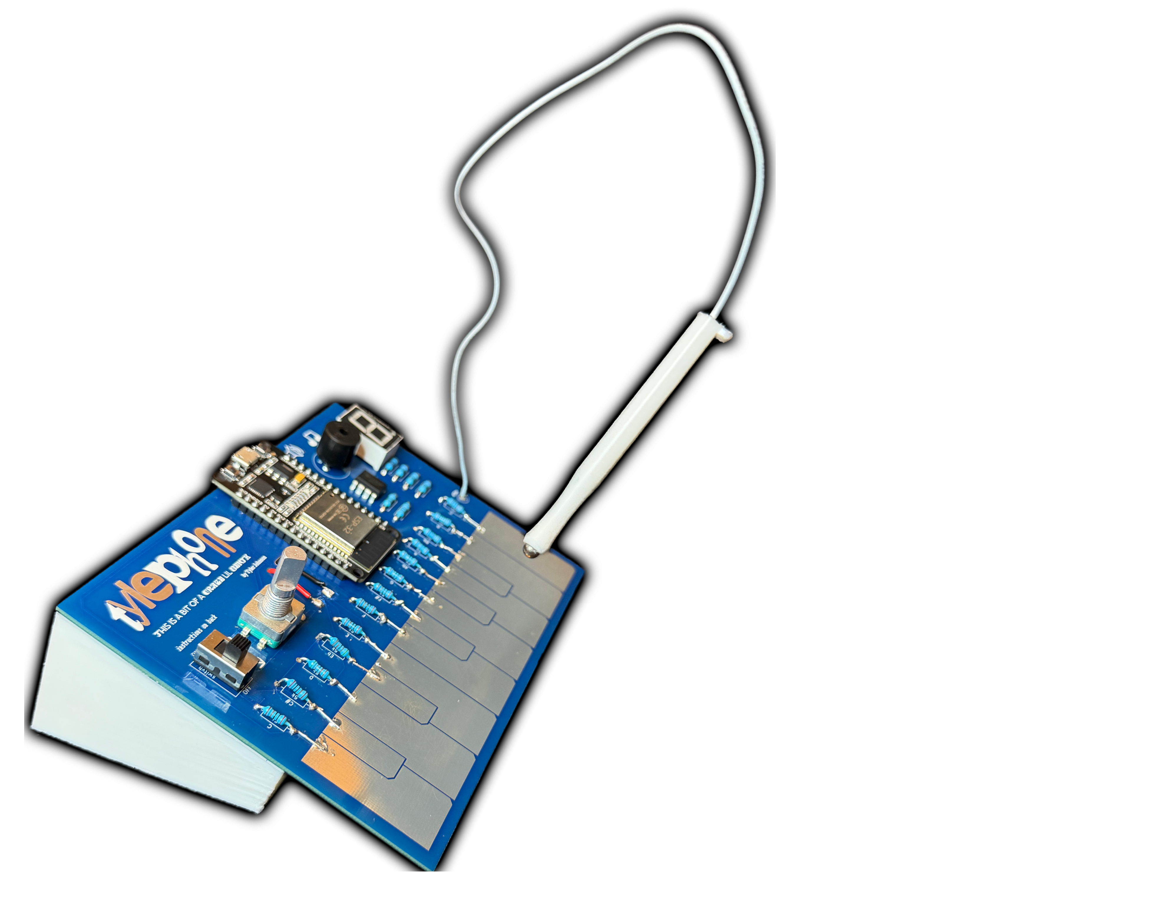
Tylephone PCB Link 5 12.53 1 2.51 Probably! I ordered PCBs that needed some home mods. I have since updated the files but never bought them myself
ESP32 board Link 3 16.79 1 5.60 YES
5kohm resistor Link 30 9.99 13 0.21 No, but as long as they're 1/4W, something close to 5k will work just fine
220 ohm resistor 60 4 0.06 No, but I used 1/4W 220s in my project
100k ohm resistor 30 2 0.03 No, but I used 1/4W 100ks in my project
7 seg display (common cathode) Link 10 9.99 1 1 No, but it needs to be common cathode
LM358 op amp Link 50 6.99 1 0.14 YES
Piezo buzzer Link 10 5.99 1 0.60 Nope, and the spacing between holes needs to be .25" If that's true, should be fine
Rotary endocer LinkLink 10 10.99 1 1.10 Nope, but this measures the same size
On/off switch (SS12D10) Link 8 9.99 1 1.25 YES
battery holder Link 4 6.99 1 1.75 YES
AA batterys Link 20 8.98 4 1.80 cmon, they're batteries
Stylus wire Link 180 ft 15.89 .75 ft 0.004 YES BUT DON't BUY - it's prettty stiff. If you have a nice braided cable, or a bendy rubber cable and better soldering skills than me, you might be more successful with better more bendy wire
ball bearing Link 20 6.99 0.125 0.04 No, but as long as the balls measure about 4mm dia you'll be good
Magnets (6mmx2mm) Link 60 7.99 1 0.13 YES
TOTAL $130.10 $16.21

Tools
Description Link Full Qty Cost
super glue Link 20g 7.99
soldering iron/solder Link 1 7.89
3d printer Link 1 249.98
filament Link 1kg 12.99
TOTAL $278.85

Finally, a build guide

  1. Acquire all tools, components, and files
    1. The 3D .stl files are more optional, but I've got no other way to secure the batteries. The rest of this guide assumes the stand is used.
  2. Solder all components to the board. If you're printing the stand, do NOT solder the battey holder
    1. The ESP32 should have the USB oriented towards the top of the board
    2. The piezo buzzer should have the "+" to the LEFT (next to the printed "+")
    3. All resistor spots are labeled
    4. The LM358 should have the half-moon oriented to wards the top of the board
    5. The sTYlus wire can be soldered to it's hole, but make it pretty long (close to a foot)
  3. Upload the code to the ESP32
    1. Download the Arduino IDE (or use the online version, Arduino Cloud)
    2. Plug the ESP32 into your computer using a micro-USB cable
    3. Open the .ino code file in the Arduino IDE (either opening the file or copy+pasting the code into a new file)
    4. Change the board type to an "ESP32 Dev Module"
    5. Upload the code to the board
  4. Test that the Tylephone works while the cable is still connected. The cable bypasses the on/off switch, so it should work now!
  5. Disconnect the cable
  6. Attach the batteries
    1. Glue the edge of the 3d printed stand to the Tylephone
    2. pass the wires of the battery holder through the back of the stand and through the battery holes
    3. The red wire connects to the pad with the "+" next to it, and the black wire goes through the slit shaped like a "-"
    4. solder the red and black wires onto the pads
    5. glue the battery holder into the slot on the stand,
  7. Glue a magnet into the bottom of the sTYlus slot
  8. Assemble the sTYlus
    1. Slide the 3D-printed stylus over the wire
    2. Dissasemble the ball bearing and clean one ball
    3. Solder the wire to the ball
    4. Glue the ball into the stylus
  9. DONE